Tips and Trick sederhana cara membuat propeller dengan menggunakan software 3D CAD SOLIDWORKS,
OK kuuyy.. Langsung aja gaeeesss,…
Open SOLIDWORKS
Buka bagian baru dengan unit model yang diatur ke milimeter.
Create a new part
Buka: File> New> Parts ![]()
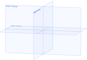
Pilih 3 planes di feature tree (tahan
tombol Control) dan membuatnya terlihat dengan mengklik pada kacamata. ![]()
Buat part baru di Right plan
Klik ikon 2D Sketch untuk membuat sketsa baru ![]()
Klik pada opsi Normal Ke untuk memutar dan memperbesar model ke normal ke Plane yang dipilih ![]()
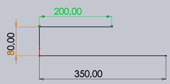
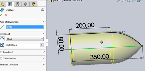
Gambarkan tiga garis lurus seperti yang ditunjukkan pada gambar. Garis 350mm harus ditempatkan pada sumbu tengah dari Bidang Kanan.
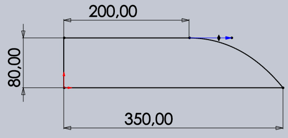
Gambarkan spline seperti yang ditunjukkan pada gambar ![]()
Tambahkan hubungan singgung pada transisi antara garis horizontal dan spline
Pilih garis horizontal, tahan tombol Control dan pilih spline. Klik pada ikon Tangency
di bar Tambah Hubungan untuk menambahkan hubungan singgung antara garis dan spline.
Create a Revolve
Go to: Insert > Boss/Base > Revolve atau click on the revolve icon Axis of revolution : Pilih garis hijau seperti di tampilkan gambar dibawah ini, select OK
Buat Sketch baru di TOP Plane
Select the Top Plane in the Feature Manager klik on the 2D Sketch icon untuk membuat sketch
Buat 3 Point Corner Rectangle Go to Tools > Sketch Entities > 3 Point Corner Rectangle atau klik di 3 Point Corner Rectangle icon Draw the rectangle seperti tampilan gambar disamping 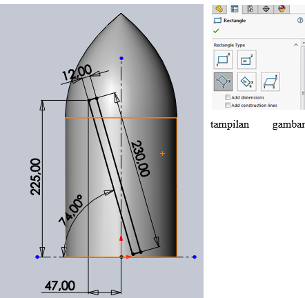
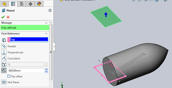
Buat plane baru
Go to: Insert > Reference Geometry > Plane or click on the New Plane icon First Reference : Select the Top Plane ganti Offset Distance to: 360 mm.
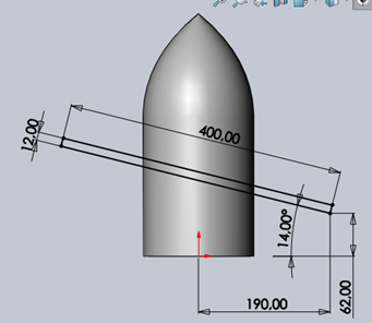
Buat sketch baru di plane 3 Point Corner Rectangle seperti tampilan gambar
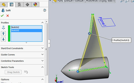
Pilih feature loft
Go to: Insert > Boss/Base > Loft or click on the Loft icon ![]()
Klik di kotak Profil ![]()
Pilih Sketch2 dan Sketch3 seperti yang ditunjukkan pada gambar Pastikan bola-bola hijau berada di persegi panjang yang sama sudut seperti yang ditunjukkan pada gambar dan detail lingkaran biru Jika tidak, klik dan seret satu bola ke sudut lain persegi panjang
Buat 2 radius di sisi samping loft
Go to: Insert > Features > Fillet/Round or click on the Fillet icon
Pilih 2 edges seperti pada gambar

Berikan Radius 135 mm kemudian OK
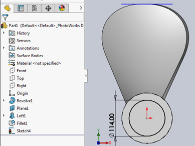
Buat sketch baru circle di surface seperti gambar dibawah dengan dimensi 114
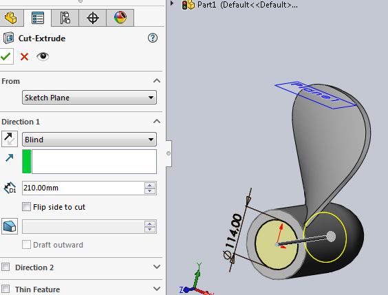
Kemudian select extrude cut dengan dimensi 210 seperti dibawah ini
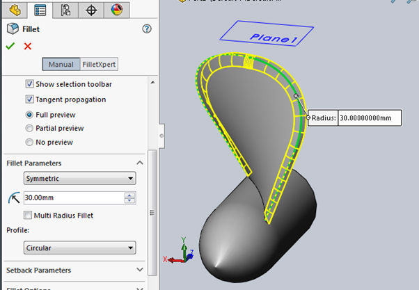
Selanjutnya berikan radius/fillet dengan dimensi 30mm seperti ganbar dibawah ini
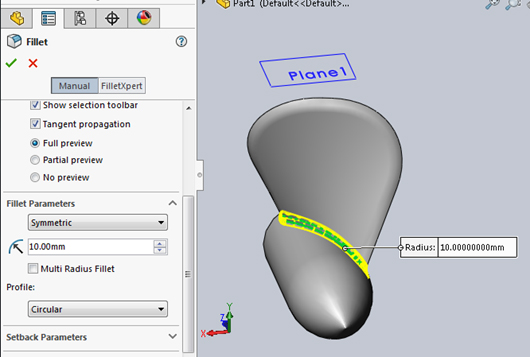
Selanjutnya berikan radius/fillet dengan dimensi 10mm seperti dibawah ini
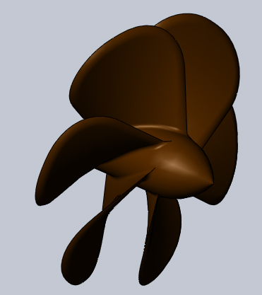
Selanjutnya perbanyak bagian loft dengan circular pattern seperti dibawah ini
Total Angle : 360 deg Number of instances : 6 Select the “Equal Spacing” option. Features to Pattern : Loft1, Fillet1, Fillet2, Fillet3 Select the “Geometry Pattern” option.

and then.. jreengg.. jreenggg. maka hasilnya akan terlihat seperti gambar dibawah ini.. Mantabss pak ekooo 😛


No responses yet